
When Ariadne got up in the fall of last year, the engine also got up. The purpose was to renovate it in the dark evenings of winter and thus ensure that its renovation would not affect Ariadne’s spring renovation schedule. How wrong I was (again). I did bilge repair, engine repair and standard spring maintenance, to put it nicely, multi-tasking, i.e. in parallel, so the text is not necessarily in chronological order.
Bilge
The spring renovation included the renovation of the bilge around the engine when the engine was not on the road. In addition to cleaning and painting, the list included the renewal of the quick repairs of the holes patched during the first spring. The renovation started with a grease wash, for which I used Bräkleen, which worked very well. So the grease left the engine and after that I removed the loose rust and old paint with a needle chipper. After the engine compartment was washed and the paint removed, I looked at the bilge forward towards the bow. In front of the engine room there are two bilge spaces, where the bilge extends right up to the bottom edge of the keel, i.e. the depth is over a meter and the width is half a meter. The part in question has caused a headache since the beginning, because drying it, not to mention cleaning and painting it, has been very laborious.
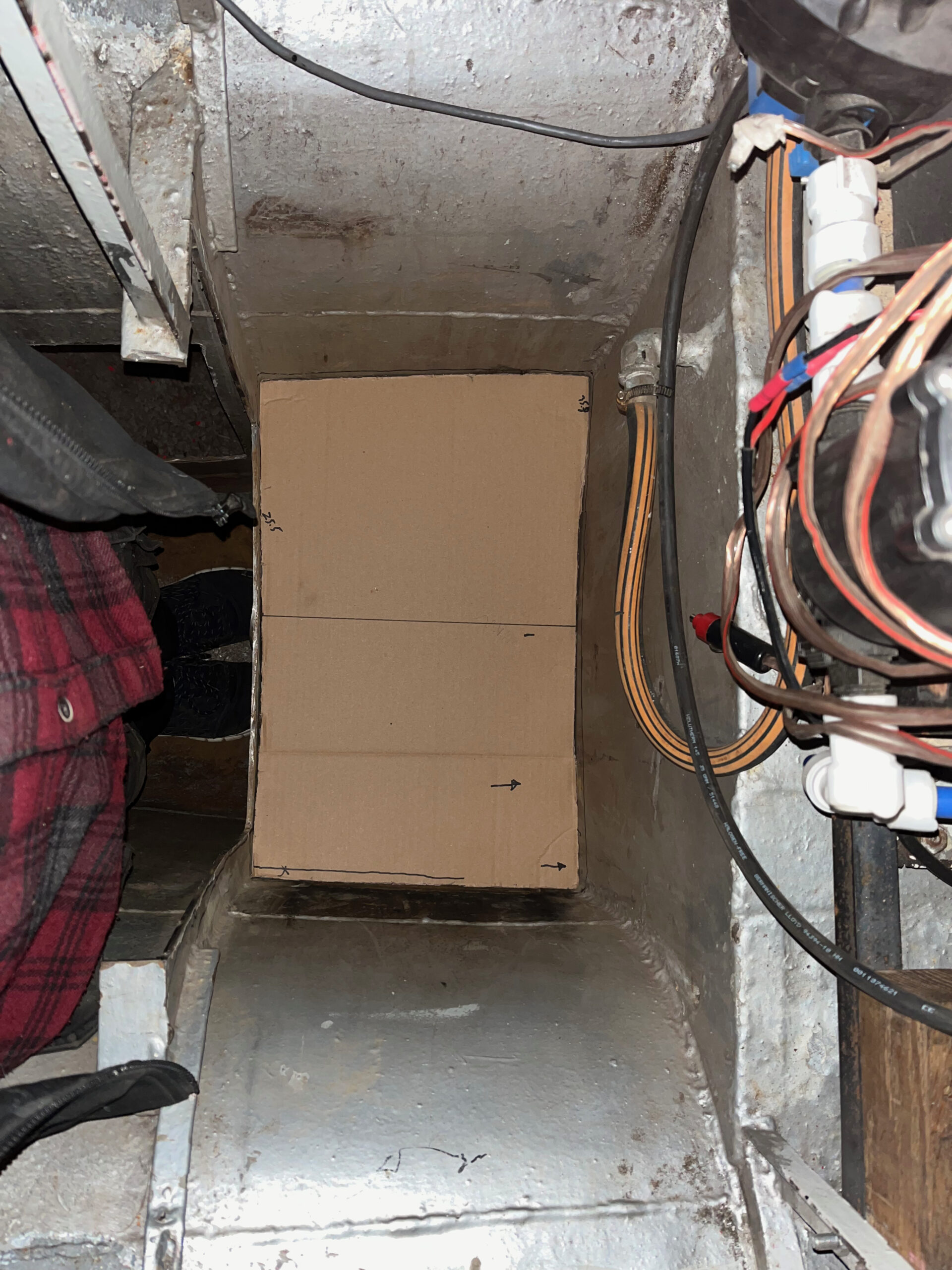
Hmmm….. if the bilge was not so deep, it would be easier to dry and keep clean and you wouldn’t have to wave a sponge or rag a couple of meters away. … quickly it could be done two intermediate soles in the bilge between the two arcs, something like halfway between …. and inspection hatches for them…. and at the same time you can remove the old cooling water inlet and its tap in the keel …. and to make a big hole in the keel for working …. and through that go through the front wall and bilge of the hull tank, i.e. go through them with a needle chipper for possible holes and for their repair and painting…. and then Zinga to the surface …. Let’s get to work. First to Rasmet Steel to pick up angle steel and 4mm and 5mm plate. I made the cardboard models from two plates of the intermediate base and made the corresponding plates from 4mm steel. For the dimensions of the inspection hatch, I used a beer basket as a model and made correspondingly sized holes in the plates and then collars for them from angle steel. For the covers to be bolted to the collar, I made threaded holes for 8mm bolts in the collar so that there is no need to use nuts. When the collars were welded to the plates I fitted and welded them in place. I welded the old piece back into the working hole in the keel, after I had first located the through hole that was in it.
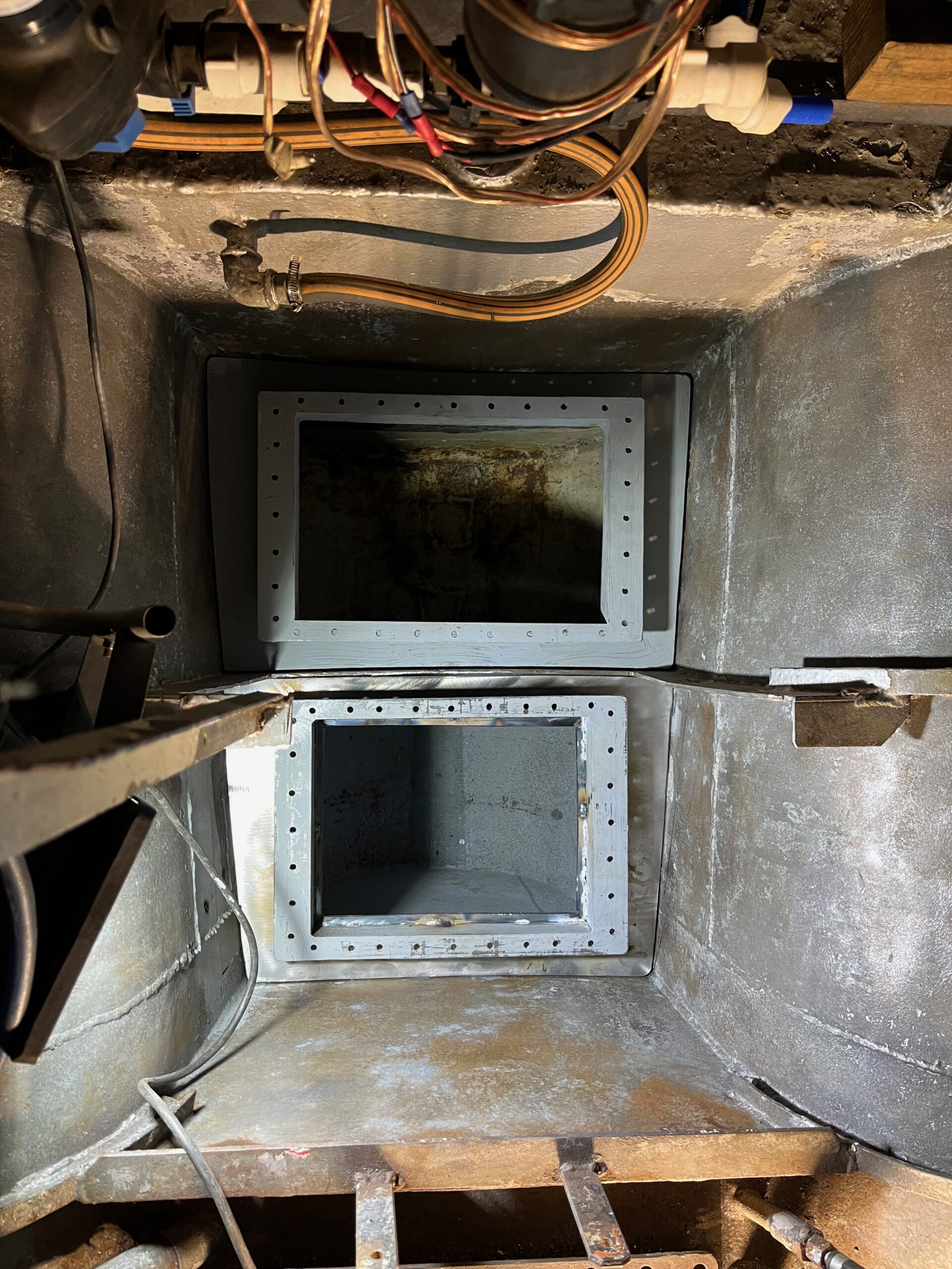
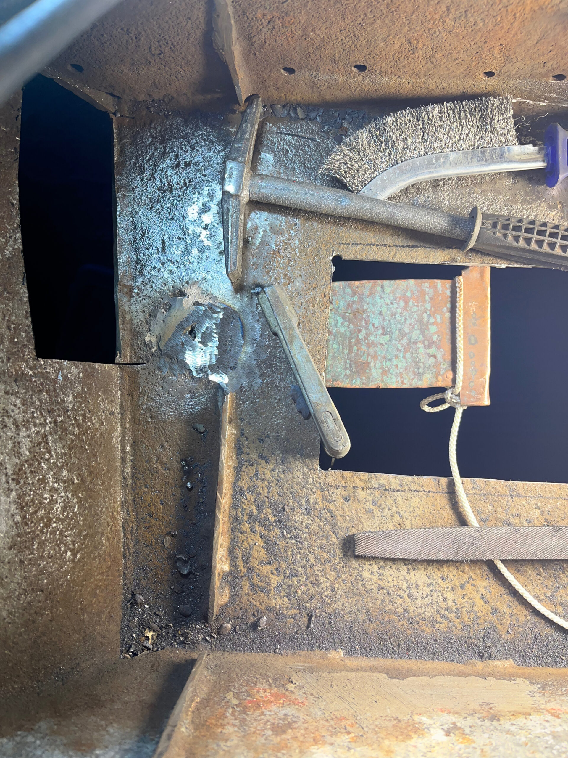
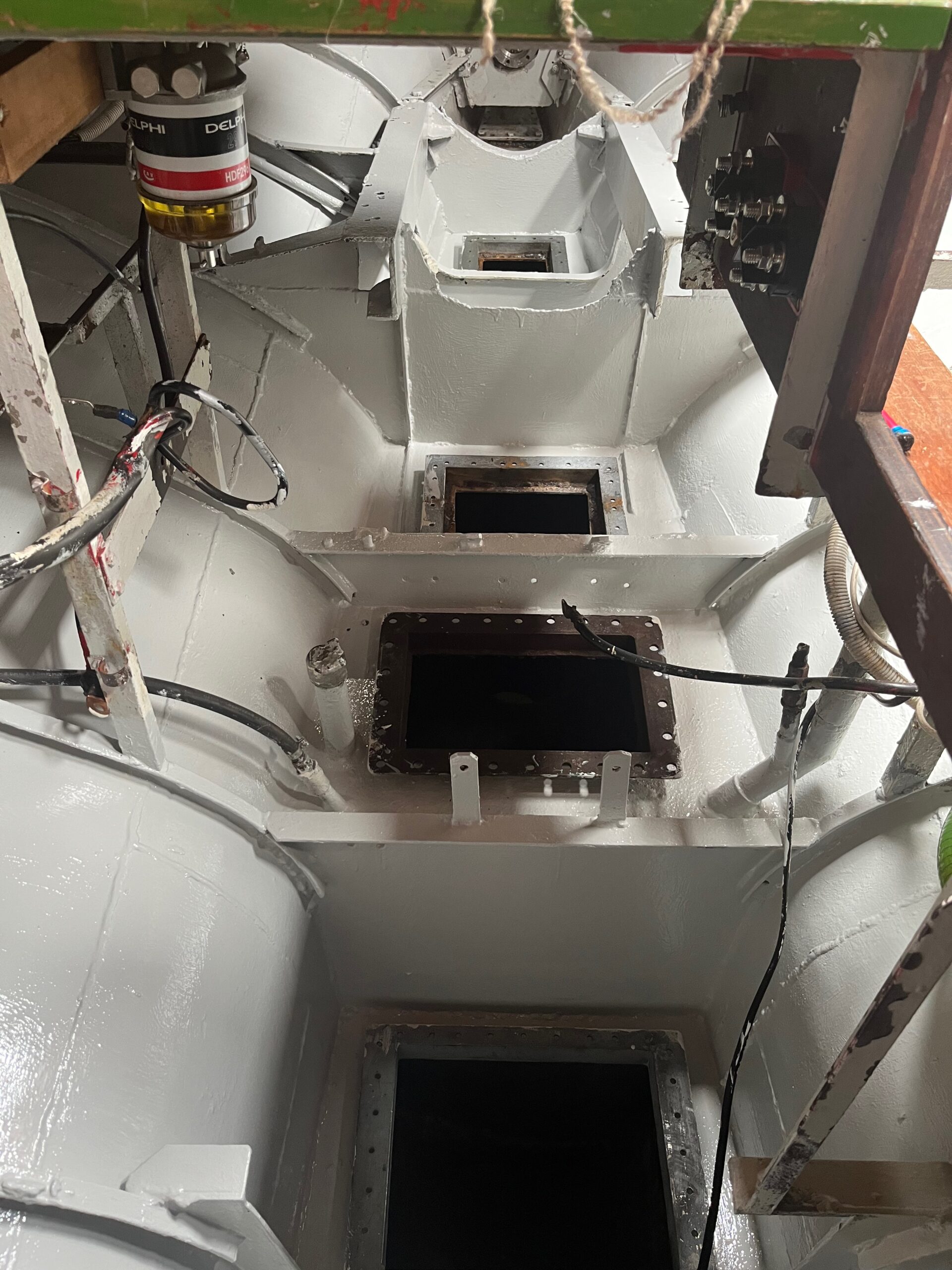 The fuel tank, which is part of the keel and has the size of three frame gaps, is placed under the engine. It has an inspection hatch in one of the frame gaps, so I also made similar ones for the top plates of the other two gaps. One of the top plates had a hole patched with epoxy and deep corrosion in the first spring. For that, I had planned to replace the entire top plate in question. After wondering for a while about patching holes in steel, I came across a project of an elderly car repairer in the internet, where holes in the car’s sheet metal were patched by welding. Welding holes is challenging, because the heat generated easily only makes the hole bigger, I do have experience with this. In the project, a copper plate was used behind the hole in the sheet metal to collect the generated heat, allowing the hole to be welded shut. I decided to try it on the top plate of the tank in question, even though the sheet was thicker than car sheets, i.e. 4mm. The copper heat collector was born from the copper plate of Johanna’s old fuel tank, which I installed around a 4mm steel plate so that its mass would be sufficient. I attached it to the bottom of the top plate through the hole I drilled at the place of the deep corrosion and wow, it worked better than well. The deeply corroded area was filled with new steel and I did the same to the corroded area. The result was neat and much easier than replacing the entire board.
When the welding work was done, I moved on to the painting work. At first I painted the cleaned part of the bilge with Zinga and then with Zinga intermediate paint for future paint layers. I put off the rest of the bilge painting a little further and the next thing on the program was sanding the sides and removing the chipped filler on the hull and applying and replacing it with epoxy filler. When the surface was satisfactory, I painted the sides once with Epiphanes gloss white. After sanding, the walls, gunwale, mast and boom received 1-2 layers of Epifanes lacquer, i.e. a little too little. The outer surfaces were now somewhat taken care of and all that was left was the further painting of the bilge. Fortunately, not completely, but around the engine and the couple of arc gaps where Zinga’s intermediate finish was. On top of it I painted Inerta 5 epoxy paint and Teknodur’s two-component polyurethane paint as a topcoat.
The engine compartment was finally ready to receive the engine and the exterior was just about ready for launch, the only thing missing was the antifouling paint. It was painted by Niina the weekend before the launch date, i.e. a week before Midsummer.
OM636
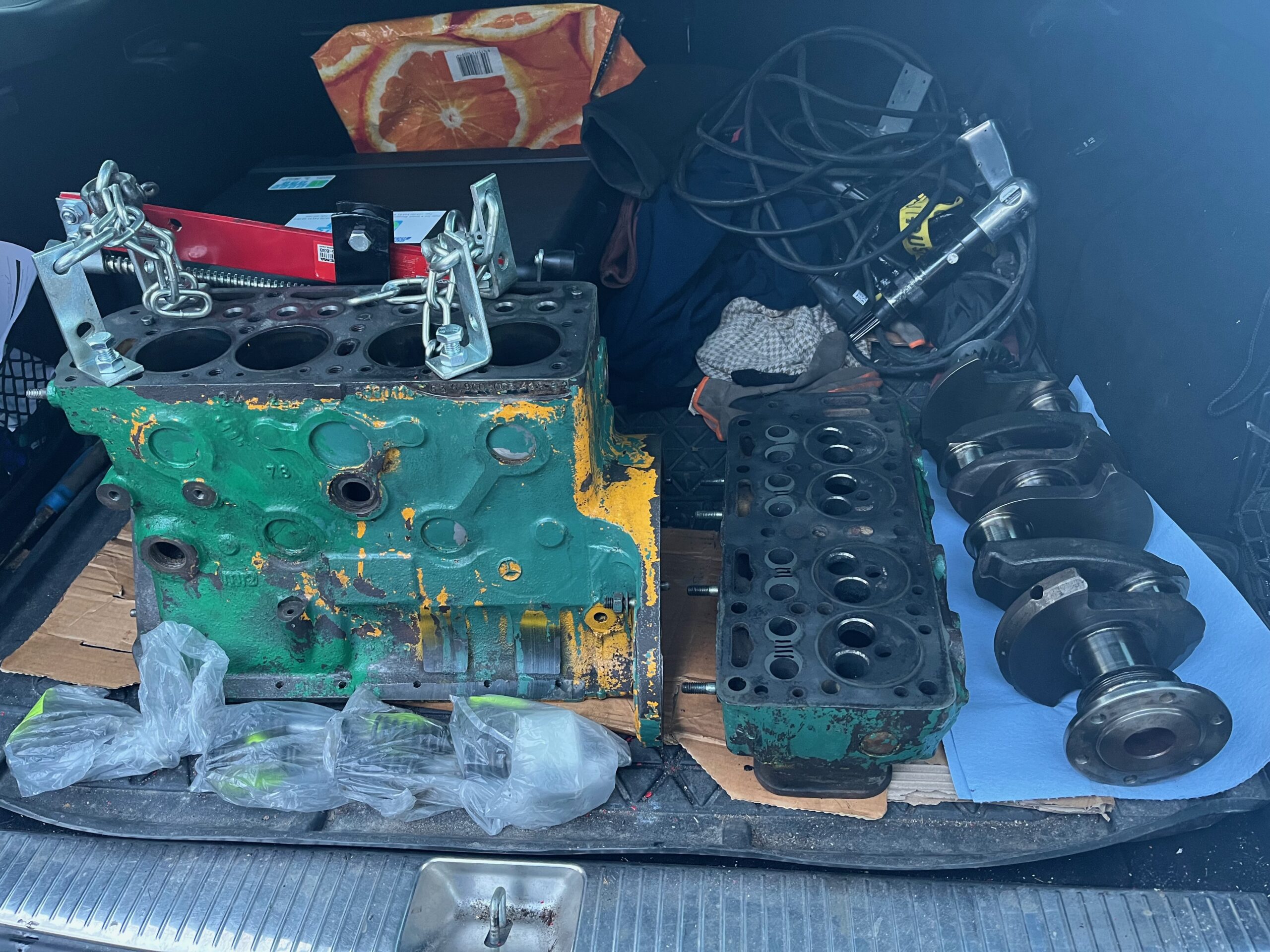
After the engine moved to the garage in the fall of 2022, it was slowly spread around the garage in parts. I took the cylinder head, cylinder block and crankshaft to the machine shop in Kerava that Dieselmies Oy had recommended. The diesel man picked up the nozzles and returned them serviced after a week with a little higher opening pressure because I had talked to him about the pre-chambers. The original ones had balls, the new ones didn’t. He said that without balls, it might smoke a lot and blow acrid smoke – a lot. At the same time, I showed him the injection pump in case he had any information about its adjustment or internal life. He had never seen anything like it and wanted to take another picture. In the machine shop, the head and valves were machined and the cylinder block was drilled/honed to the first oversize, i.e. 75.0mm -> 75.5mm. The crankshaft was found to be in standard dimensions, so there was no need to do anything to it. The camshaft controlling the valves was also of standard dimensions and I did not change its bearings because there was no play in them.
The thin brass body of the heat exchanger cap came off the heat exchanger with a light tap, so a replacement part had to be found for it. I finally found one in the UK, so I sent a 50,- order to them, which was duly acknowledged. So it ended up in Inkoo via work, because I used the work address as the delivery address for the orders, so there was no need to worry about timing of the delivery at home. Fortunately, work was manned from 08:00 to 16:00 on weekdays. The installation of the part was its own project, because part of the old cap frame was still in place and the heat exchanger was aluminum. By myself the job would not have been successful without many tricks, and in the end I contacted a local machine shop called Inkone Oy. There, too, the matter caused some thought, but a couple of days later they called and confirmed that the body of the cap had found its place in the heat exchanger. Well done.
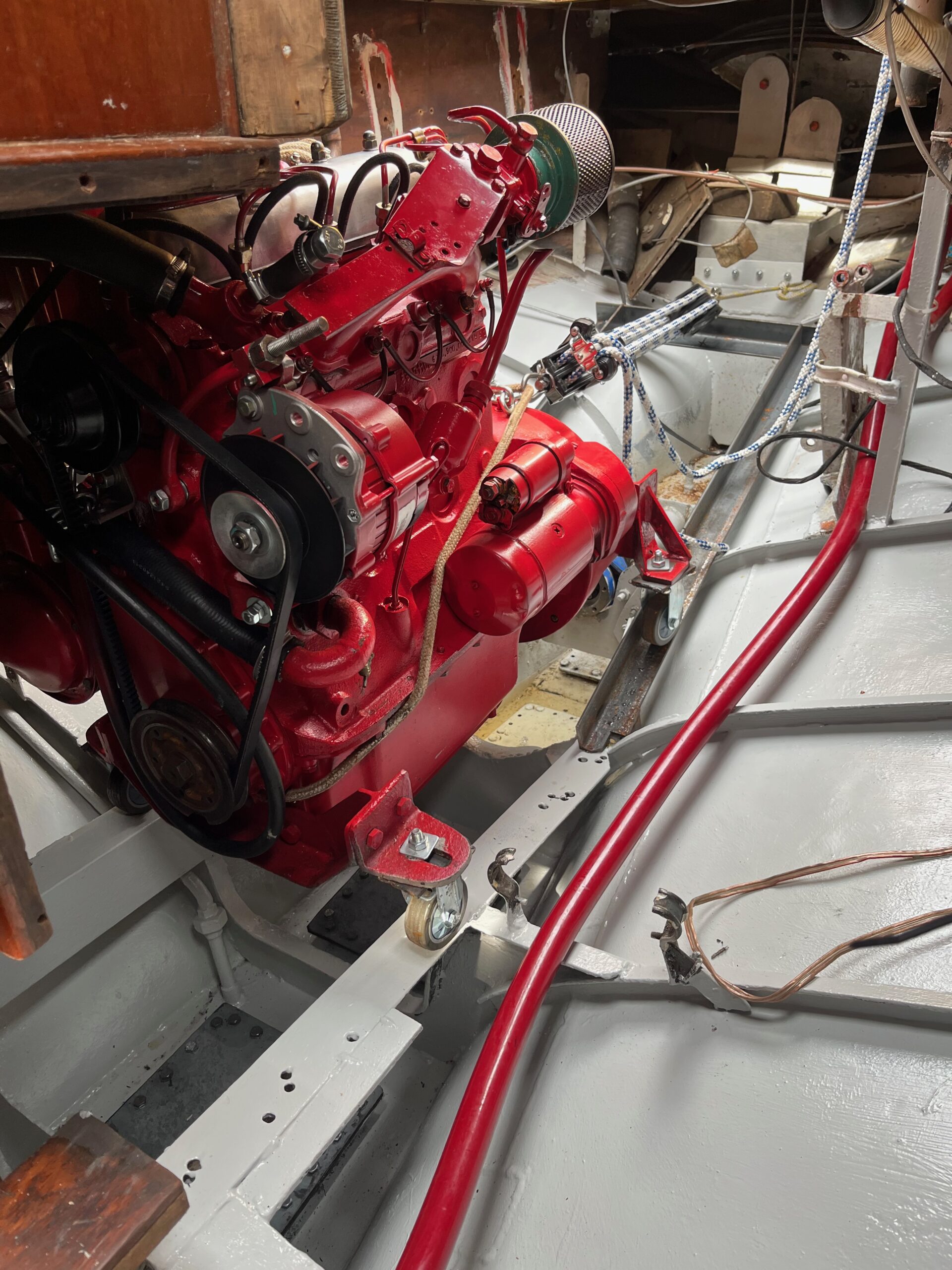
In the meantime, I had ordered a water pump from Germany, a complete set of gaskets, new pistons with piston rings and bearings for the crankshaft and connecting rods. From the British OM636 guru, I ordered new pre-chambers, thermostat housing, drive plate and fuel pipes for two nozzles. After I had picked up the parts I had taken there from the machine shop, the assembly started, and it was already May. The assembly started with painting the parts, as the old paint had chipped and peeled off and partially revealed the original yellow color. The color chosen was an honest red, the second choice would have been cream, but it would show possible oil leaks even more clearly. The first installation job of the engine was the installation of the pistons, and it normally takes an hour if you are not in a hurry and have the patience to take the necessary beer breaks. The first piston fitted with new rings in place like in the movies, “now it’s going as it should”. The second piston didn’t even go into place. I thought of a lousy piston ring press and bought a new one, a little different, this time from Bilhelvete. It didn’t help, I wasted a lot of time – a couple of weeks in total – because I assumed that there is something wrong with the installer or the method and I tried all possible and impossible techniques to get the 2nd and 3rd cylinder pistons in place. The 4th had successfully found its place like the 1st cylinder piston.
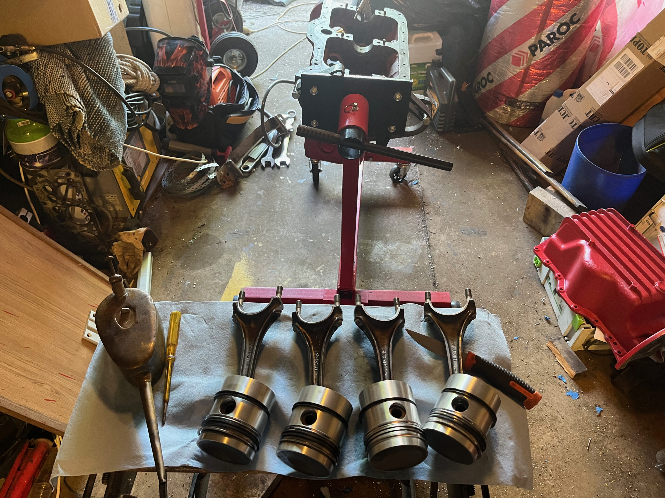
I was already thinking of complaining to the machine shop that they had left the 2nd and 3rd cylinders unhoned… until I paid attention to the piston rings of the problem piston and the last oil ring, which always got stuck. Different ring head than the old ones…. how about the 1st piston….. similar to the old ones… the 4th piston… similar to the old ones…. on the 3rd piston…different ends. Goddamit, the ends of the oil rings of the new pistons had been left in the stage of their manufacture, so to speak, i.e. they had not been finished – China quality? I hadn’t noticed it because the rings were in place on the pistons and I had assumed they were as they should be. Complaining to the piston dealer? I quickly ended up ordering a new set of piston rings from Germany, I would receive them in a week. It would take the whole summer to complain, so I refused to even try it. After receiving the new piston rings, I replaced them all on all pistons. Now the pistons were installed in half an hour, but midsummer was near.
Midsummer
The shipyard is usually closed on Midsummer for the holidays, but luckily they told me that they would be working for at least a week after Midsummer. Ariadne was launched during the midsummer week and originally the engine should have been moved into place at the same time. Of course, this was not successful, because the assembly of the engine was badly delayed. The pistons were in place, but next the crankshaft installation did not succeed. It did go into place, with new bearings. The rods sat in place as they were supposed to. When I tightened the crankshaft bearing clamps to the correct torque, the shaft no longer agreed to rotate……. Wrong bearings? …. were absolutely correct because the old ones had the same problem. The week was spent wondering and trying to install. Until finally I came across the phrase on a youtube video of an OM636 repair. “the textile seal on the crankshaft end was left unreplaced because the new seal might cause problems”…. I had replaced it and that’s where it apparently caused the problem. I decided to impregnate it even more in oil and finally I got the shaft rotating satisfactorily. After that, assembly progressed quickly, although midsummer had already passed.
I had marked the position of the injection pump, i.e. in practice the timing somewhat precisely and I trusted that it was correct. Oils and coolants in and running? I got the engine going, but after a few minutes it was difficult to find the way out of the garage, the light gray smoke was unbelievably thick. Hmmm… the timing seems to be a bit off….
Fortunately, at the boatyard, Emil said that he would still be at work for the next week… and the calendar showed mid-July. You have to get the timing of the injection right, but how.
The old OM636 manual in German described how to get the timing right with the drip method. “You have to try, even if it seems confusing. “Its logic and the working principle of the old diesel in-line pump slowly became clear, the pump found its position according to the instructions and finally it worked and didn’t smoke! Finally,
I went to get a universal and more efficient alternator from Motonet to replace the original one, and it did fit surprisingly easily. At the same time, I also made a new gauge panel for the engine, as its assembly grew with an oil pressure and day tank fuel gauge.
Mast
The 10mm forestay inside the roller genoa profile was the only wire that was not replaced in 2017, and since finding out its condition had been on my mind for a long time, I decided to see how it looked. It was probably more than a decade old because the composition seemed quite original. Dismantling the roller device itself was easy, but removing the cable from it required a few working days. All 19 strands were intact, but since it had now been disassembled, it obviously had to be replaced. The only time-consuming step in installing the new cable was fitting the end of the cable and the cone inside it into the roller device. The straightening of the strands in the initial stage could have been omitted, as it was practically impossible. In the end, the strands of the cable were neatly in place and the assembly of the roller device itself did not take long. I still removed the extra cables from the mast and used the old cable for the engine light to pull the new cable in question. I shouldn’t have, because of course it broke because it was in the wrong place inside the mast in the first place and pulling a new one even with the tension spring I tried was a doomed attempt. For this reason, I pulled a new cable up to the top inside the mast and from there down to the engine light as a surface pull. The surface pull of the thin cable was irritating to the eye, but in practice no one else can see it but me, so the end result was tolerable. Finally, I sanded the mast and boom and varnished them twice.
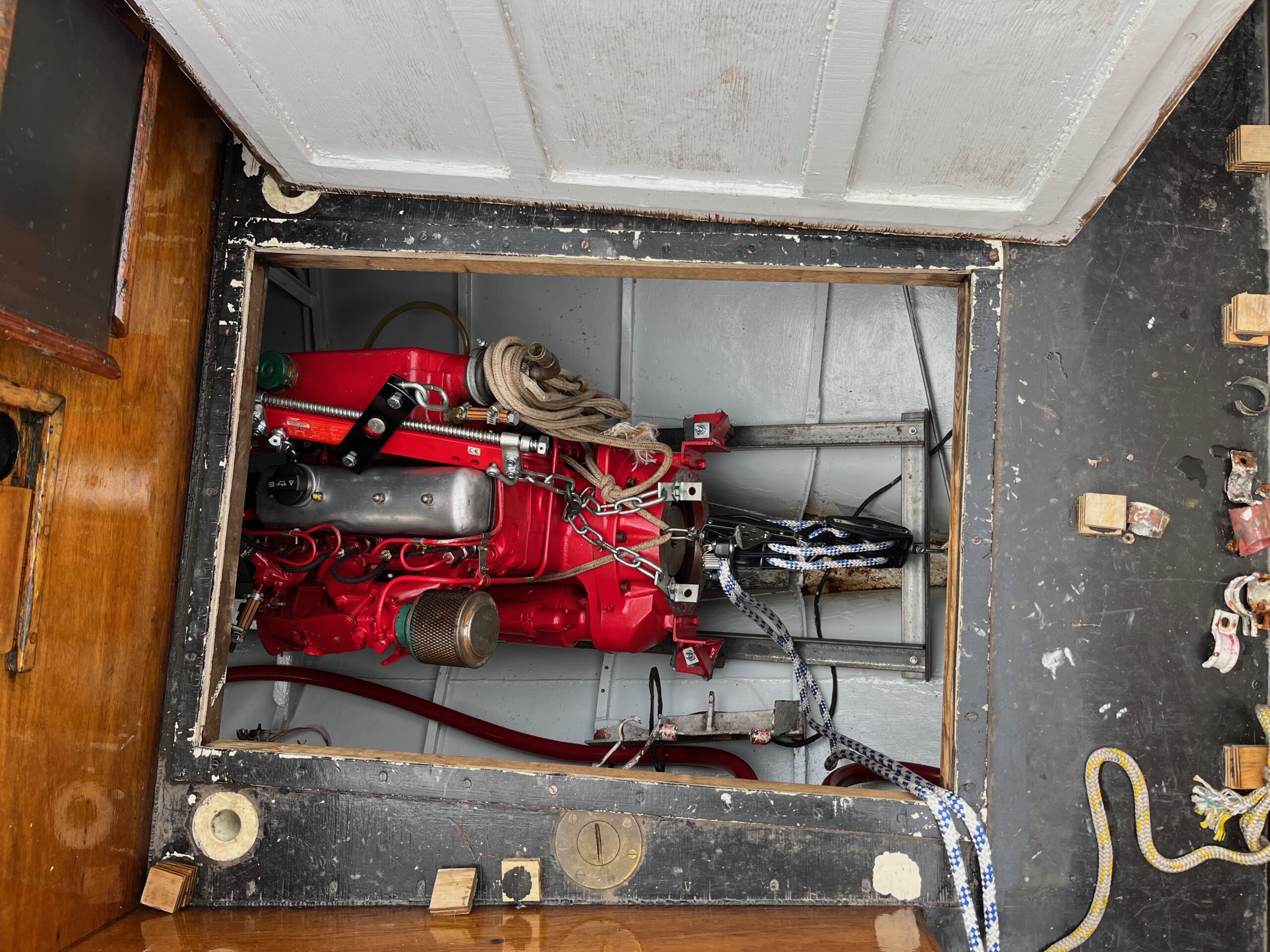
Engine installation
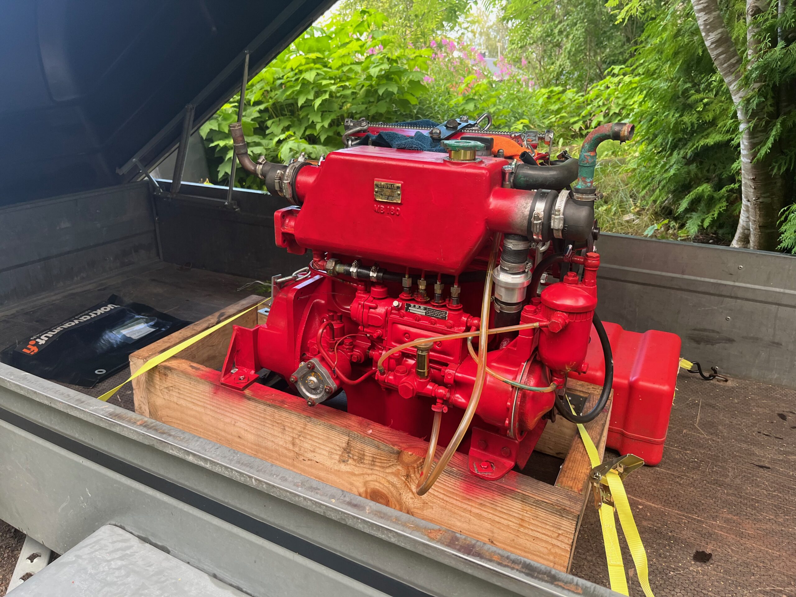
Finally, it was time to install the engine on the boat and it went smoothly as the engine moved down from the hatch of the silo with the help of the dock’s mast crane trailer and finally onto the wheels in place of the engine pads along the rails. Once the engine was in place I replaced the wheels with rubber pads and after that I started installing the exhaust pipe. I had left the muffler and the bend of the exhaust pipe that mixes seawater into the exhaust pipe to cool it down in the shipyard’s hangar at Ariadne’s place. After searching for a while, I found that the bend had disappeared, luckily the muffler was still in place. When I had dug out the garage several times and searched the backyard too, I had to admit that it had found a new life somewhere else. There weren’t any new parts for the 70s engine on the shelves of every store, and in the end I turned to the British OM636 guru that I had already become familiar with. “Yes, there are bends, shall I send?” I got a reply when I inquired about availability. Bueno.
There’s enough – sh*t, too much – heat
The bend arrived, and I finished the engine installation, although the calendar already showed mid-August. I had also updated the engine panel to be a little bigger because I had added two gauges to it, the oil pressure and the fuel level in the day tank. Hopeful, I started the boat, the sea water came out of the exhaust pipe as it was supposed to and I already started planning the departure to the home port. The oil pressure also seemed to be ok, i.e. 5 bar. Just to be sure, I let the machine run long enough to make sure the thermostat was working and that there was no longer an air lock in the cooling system. In the spring, engine had always had symptoms of cooling water circulation problems and it resulting too high operating temperature. It was always gone after a few days of trial use. As far as I understand, I had now fixed the problem, because during the dismantling process I found a thin tube blocked in the cooling system near the water pump, which was completely blocked and which I cleaned. The temperatures now rose slowly to 60-70-80-90??!???-100… no …sh*t… the same overheating problem still. It can’t be… yes it is…. after a few days of tests, I had to believe that the problem was also of permanent quality.
This can’t be true, the cooling ducts were clean, the blocked ventilation duct was also cleaned and on top of that I had ordered a new thermostat and also its housing to replace the old 50’s closed design…. Faulty piston rings came to mind…. could there be something wrong with the new component? The thermostat was the only unknown factor so let’s do a little research. Again, studying pictures of similar engines and going through the cooling system. In other versions, the thermostat seemed to be in a different branch of the cooling system. I interviewed the British guru again and according to him, WM engineers did know how to design the OM636 system to work. The only thing that should be checked is that the thermostat is facing the right way in its housing, i.e. it opens in the direction of the flow. Alright, I thought and removed the glycols and opened the thermostat housing. The thermostat was facing exactly the right way, as long as the housing was installed in a different branch than in Ariadne’s engine. Since it was now in the other branch, the flow was reversed, so I turned the thermostat, filled the system with glycol and started the engine. The temperatures rose slowly to 60-70-80-78-78-78-78!!!! The heats were ok.
It’s moving
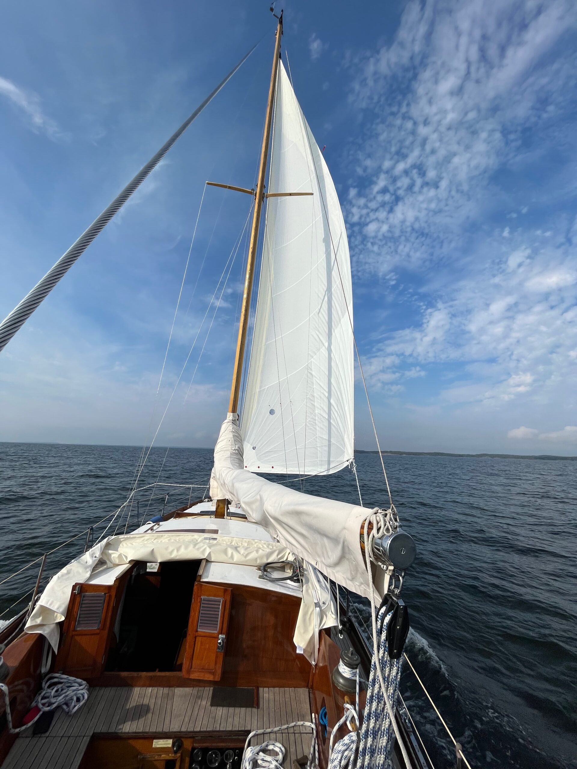
In the calendar, the month had not yet changed to September, so there was still summer left. Small adjustments were still needed, as I had moved the day fuel tank to the other side under the bench seat so that it could be accessed a little easier. The transfer required a frame for the tank, because the hull was bending in all possible directions and I wanted the tank to be horizontal and stay in place. The frame was made from angle steel that rested on the arches of the frame. For that, the stand came with four legs that were all different sizes. Making fine art would have been child’s play compared to determining leg lengths. Before installation, the day tank had to be emptied and vacuumed, because there was too much bacterial growth on the bottom. It had successfully managed to mess up the filter that had just been replaced during the first test runs, so the filter cartridge was replaced again with a new one. Finally, Ariadne moved to her home port on 27.8. as the adjustments continue. The engine temperature and oil pressure both remained at good readings, during the full-day drive the temperature remained at 80C degrees and the oil pressure at exactly 4.5bar, and after that at home it was still 2.4bar even at idle. All good. The end of the sailing season came on September 9. and Niina and I turned Ariadne’s bow towards Lähteelä on Saturday morning. The wind remained consistently light and contrary, and therefore the journey was made entirely by engine power. Saturday’s program went as usual, as did Sunday, when we went to the bird tower to admire the scenery. On the way back to Inkoo, we hoisted the new genoa, which unfortunately will not be properly put into action until next season.
Ariadne moved back to the boatyard at the beginning of October and the mast was taken down on October 3. On the same day, I changed the oils myself and ran the glycol to the seawater side of the cooling system. Ariadne got up the very next day and, after washing the bottom, moved to the hall to wait for the coming spring. I should still put another boat and summer cabin for winter break.
Summa summarum
The decision to rebuild the old engine caused some interesting discussions, as my choice generated some wondering “why not a new one instead?” The main reason for that was that I wanted to minimize the need for electricity as a prerequisite for the engine to run. Starting an old diesel obviously needs electricity, but after that there is no black box to measure the engine parameters and decide whether the engine can run or not. One VP engine series comes to mind, whose fine and advanced engine control electronics were bolted to the engine block and thus exposed to constant vibration. This, in turn, caused the engine to shut down while running. Before the final decision, I also collected all possible and impossible manuals regarding 1950-1960’s MB diesels and Bosch diesel technology. Since there were many manuals available and since there were several online stores in Germany selling spare parts, the decision was finally easy. To sum up the work of the engine and bilge, you could apply, for example, this woodworking tip “measure twice, saw only once” sum it up to “don’t assume anything, check yourself and always at least twice”. And of course, regarding the schedule, “if you want to get all the work on the to-do list done, drop at least half of the work to be done”. What are the costs? Typically, they do not calculate a price for their own work, and that’s fine.
Engine repair costs:
Machine shop approx. 1,200
Refurbishment of nozzles 370
Pistons with piston rings 680
piston rings 313
bearings 355,-
pre-chambers, injector pipes (2 pcs), traction plate, thermostat, 712
cylinder head bolts, gasket kit, fuel hand pump 258
water pump 151
Body and installation of the heat exchanger cap 150
alternator 100,-
exhaust pipe bend and hose 215
Paints 45,-
A total of 4549 Next spring’s to-do list is surprisingly short, have I already learned something? In addition, the approaching spring will be different, because with these prospects I will already be retired by then. Whether it will be better or worse for the restoration of the boat remains to be seen….